
To pick up where I left off in part 1 after piece part inspections, we start from the inside out.


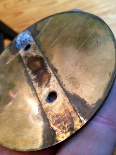
A quick sanding would prove very effective in corrosion and gunk removal as shown below.


Then repeat to all the associated fits making sure to simply clean the surfaces, not change any clearances.


After cleaning the main center barrel which had more than enough buildup to stick any bufferfly, let alone the crazy shaft and mounting holes above, I thought about removing the piece inside the housing. I decided to just clean it up and leave it alone as I would probably damage it during disassembly and there was no reason to break this down any further.


The butterfly itself was just as comical.


It's amazing how far a little sanding and cleaning will push.


Repeat on the other side.


Take a break.


I moved on to assembly.
Close up of the adapter with set screw hole. This goes between the butterfly shaft and tps and lets you adjust the flat position of where the tps reads.


Greased the moving parts.


Cleaned the spring spindle.


Spindle on shaft.

Spring on spindle.

dEW break.

Shaft in housing, idle screw and mount in place.


Butterfly in place. You'll have to rotate the shaft around in order to insert the butterfly into the slot and bolt it down. This can be a slightly irritating process with the spring connected already and a lack of another set of hands. If you put this in the wrong direction, it won't be even close to closing. Take care not to strip threads as this would be a pain.


See above for a butterfly in the wrong orientation. See below for it in the correct orientation. Note the difference in gap when closed.

The flat on the shaft itself is parallel to the face of the butterfly itself.


When the adapter is installed with the setscrew on the face of the inner flat, the flat of the adapter is turned 9o* from the butterfly face. You could install the adapter in another position, but this would affect how the tps reads the butterfly position.
There is some adjustment of the tps once it's mounted on the ring, but not much. I was a bit worried that if I had to adjust the tps more than the mounting ring would allow, I may have to grind a new flat into the inner shaft in order to rotate the adapter itself. In theory, if the adapter was rotated far enough, the set screw would fall past the inner flat entirely and sit directly on the round shaft. I wasn't sure if enough tightening would keep it in place or not when installed this way. On the other hand, if it wasn't rotated enough off the inner flat, the set screw would sit at an angle and not seat which wouldn't be good for anyone. Hopefully this wouldn't be needed.
I'm pointing all this out specifically because one thing that may have been happened to induce this non-boost madness was the adapter rotating on the shaft as compared to where it should be, or where it started from when tuned. The tps would read incorrectly causing all sorts of issues. The original throttle body evaluation entry months ago has lots information on this and how I kept it in position as compared to the g35 throttle body which is what it was tuned with.

Installed the tps. I had to get some washers to space it out from the mounting ring because of some features on the underside that wouldn't allow it to sit flush. To everyone's delight, this will be covered in more detail in part 3. Previously the tps was simply mounted and torqued town.


Back in the garage, I cleaned the face of the plenum. I tried to install the throttle body without any rtv as I did not want the same results as last time.


I can definitely report I didn't get the same results, but I wouldn't recommend this approach. Even at idle pressures, she wasn't holding air without some sort of seal. 2o/2o hindsight, it's obvious that two un-machined surfaces in a joint aren't going to seal without some intervention, but I gave it a shot. Lessons learned and all that jazz.
From here I wired the maf where it was frayed.

Connected the maf adapter pipe, installed the assembly, and tightened down the clamps.
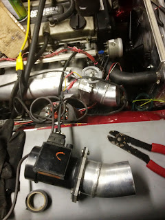

At least it looked clean, but it was far from finished at this point. Little did I know that I would remove it 4 more times in the same evening to troubleshoot and alleviate various issues.


A quick sanding would prove very effective in corrosion and gunk removal as shown below.


Then repeat to all the associated fits making sure to simply clean the surfaces, not change any clearances.


After cleaning the main center barrel which had more than enough buildup to stick any bufferfly, let alone the crazy shaft and mounting holes above, I thought about removing the piece inside the housing. I decided to just clean it up and leave it alone as I would probably damage it during disassembly and there was no reason to break this down any further.


The butterfly itself was just as comical.


It's amazing how far a little sanding and cleaning will push.


Repeat on the other side.


Take a break.


I moved on to assembly.
Close up of the adapter with set screw hole. This goes between the butterfly shaft and tps and lets you adjust the flat position of where the tps reads.


Greased the moving parts.


Cleaned the spring spindle.


Spindle on shaft.

Spring on spindle.

dEW break.

Shaft in housing, idle screw and mount in place.


Butterfly in place. You'll have to rotate the shaft around in order to insert the butterfly into the slot and bolt it down. This can be a slightly irritating process with the spring connected already and a lack of another set of hands. If you put this in the wrong direction, it won't be even close to closing. Take care not to strip threads as this would be a pain.


See above for a butterfly in the wrong orientation. See below for it in the correct orientation. Note the difference in gap when closed.

The flat on the shaft itself is parallel to the face of the butterfly itself.


When the adapter is installed with the setscrew on the face of the inner flat, the flat of the adapter is turned 9o* from the butterfly face. You could install the adapter in another position, but this would affect how the tps reads the butterfly position.
There is some adjustment of the tps once it's mounted on the ring, but not much. I was a bit worried that if I had to adjust the tps more than the mounting ring would allow, I may have to grind a new flat into the inner shaft in order to rotate the adapter itself. In theory, if the adapter was rotated far enough, the set screw would fall past the inner flat entirely and sit directly on the round shaft. I wasn't sure if enough tightening would keep it in place or not when installed this way. On the other hand, if it wasn't rotated enough off the inner flat, the set screw would sit at an angle and not seat which wouldn't be good for anyone. Hopefully this wouldn't be needed.
I'm pointing all this out specifically because one thing that may have been happened to induce this non-boost madness was the adapter rotating on the shaft as compared to where it should be, or where it started from when tuned. The tps would read incorrectly causing all sorts of issues. The original throttle body evaluation entry months ago has lots information on this and how I kept it in position as compared to the g35 throttle body which is what it was tuned with.

Installed the tps. I had to get some washers to space it out from the mounting ring because of some features on the underside that wouldn't allow it to sit flush. To everyone's delight, this will be covered in more detail in part 3. Previously the tps was simply mounted and torqued town.


Back in the garage, I cleaned the face of the plenum. I tried to install the throttle body without any rtv as I did not want the same results as last time.


I can definitely report I didn't get the same results, but I wouldn't recommend this approach. Even at idle pressures, she wasn't holding air without some sort of seal. 2o/2o hindsight, it's obvious that two un-machined surfaces in a joint aren't going to seal without some intervention, but I gave it a shot. Lessons learned and all that jazz.
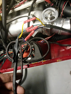
From here I wired the maf where it was frayed.


Connected the maf adapter pipe, installed the assembly, and tightened down the clamps.


At least it looked clean, but it was far from finished at this point. Little did I know that I would remove it 4 more times in the same evening to troubleshoot and alleviate various issues.
No comments:
Post a Comment