
If anyone else is counting, this will be no less than the third time I've taken off the new throttle body since TDC Auto. I guess it's a good thing they changed their name ... Heads Up Motorsports of Spartanburg, SC ... ha. But don't get be wrong, the welding fabrication on the fmic endtanks, intercooler piping, and plenum flange and throttle cable mount are great. One would think that the sensor, and butterfly for that matter, would be set like the throttle body that was replaced.


One would be wrong. You can see here that not only was the sensor not positioned in relation to the butterfly valve correctly, but the butterfly flat itself that the sensor sits on was not at the right angle, about 90* rotated between them. The plastic input hole of the position sensor also seemed to be damaged which may be part, or all, of my current sputtering issue, but I'll get to that later.


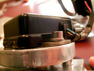
Here's the TPS set to 0% and installed over the q45 tb, the butterfly also set to 0%.

Here's the TPS still set to 0% and installed over the new tb, the butterfly of which was also, still set to 0%. The mounting points don't even line up.


Originally I was going to drill new mounting holes into the mounting ring that bolts around the butterfly valve shaft. I even went so far as to mark the new locations. I was not looking forward to either threading new holes or having to get correctly sized bolts to clear the gap between the mounting ring and the throttle body. I tested it at 0 and 1oo% positions to make sure the input shaft rotated within the range of the sensor mounted in this position, as well as having some room for adjustability.


And yes, I tried flipping the mounting ring around instead, and it would have worked except for the counterbore feature of the bolt holes that were used to mount it to the throttle body. The ring could only be installed in one direction while using the current mounting holes, not backwards. Back to drilling...

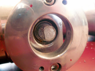
...but not for long. As it turns out, there was a set screw on the output shaft. The set screw is opposite of the flat face of the adapter that actually goes into the TPS. There was actually a flat face on the butterfly shaft as well, which was a bit disappointing as it was simply opposite of the adapters flat face.
It would have been much easier to adjust the adapter via the set screw if the flat on the butterfly shaft wasn't there, but the flat on the butterfly shaft does keep the set screw, and ultimately the adapter, from rotating independently of the butterfly. To adjust the adapter on the butterfly shaft, the set screw would have to be rotated completely beyond the flat's edge in order to be able to seat, but again, it would need another flat at that new location to stay. In theory, I could cut another flat at the new correct angle on the butterfly shaft, but I would have to know exactly where to put it which may be difficult, as there was already one flat on a small shaft. But again, the new flat would have to be at a different enough angle and center that the set screw wouldn't roll over onto the old flat, or at the very least make sure the new angle was cut deep enough to encompass the original while not loosing integrity of the shaft.
This is why I think the RB is currently sputtering at WOT. Under part throttle the fueling may not be as dependent on the TPS, but under full load the engine fueling simply doesn't work without a correct signal. This obviously can't happen if the adapter is moving all over the place because the set screw never set because I never cut a new flat onto the butterfly shaft, and simply rotated it JUST enough to barely clear the original flat's corner.
I don't want to talk about it, but I'll report back.


The adapter is rotated so that the TPS is in the correct positions and the set screw sits JUST around the edge of the flat on the butterfly shaft. Again, I did not cut a new flat, and it's currently sitting on the round edge. I use that word loosely because more than likely it's not sitting anywhere, and just spinning.


Maybe the set screw was tight enough though, as the TPS shouldn't exert too much pressure on the adapter, but if the TPS hit it's limit and locked, which could easily happen during adjustments or during use afterwards, the butterfly valve could then easily knock the adapter loose, assuming the adapter made it that far un-rotated.


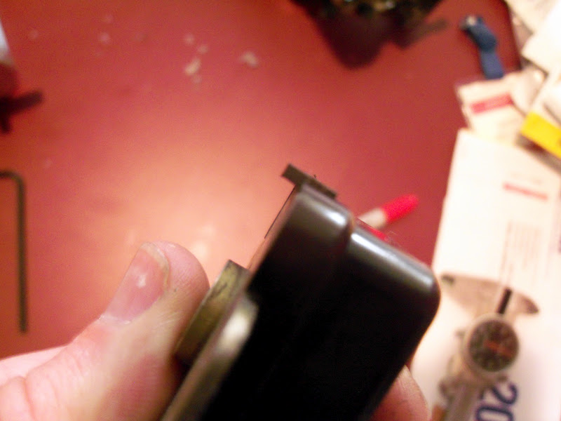
I trimmed the hanging flange from the TPS so that the sensor would sit flat on the mounting ring, not that it would matter if the shaft adapter is not set, but that's besides the point.


9o mm tb with set tps, welded radius, and reducer silicone coupler.


It looked good and ready to go.


Even got new allen hardware for the sensor mounting which would be easier to loosen and tighten while adjusting later with said wrench.


TPS finally installed.


I spent some time cleaning the faces of the intake plenum and throttle body of old RTV residue.


Got together all the throttle body hardware.


Gel locktite is amazing.


Added new RTV to the throttle face.


Installed in car.


I undid the t-clamp on the maf flange elbow in order to allow it to slip into the coupler in the radiator core support. This allowed room to install the maf and tb coupler. Finally I pulled together the maf flanges, bolting them together and attaching all the t-clamps.


Connected.


After connecting the throttle cable it was time for a test. It ran a bit rich.


One would be wrong. You can see here that not only was the sensor not positioned in relation to the butterfly valve correctly, but the butterfly flat itself that the sensor sits on was not at the right angle, about 90* rotated between them. The plastic input hole of the position sensor also seemed to be damaged which may be part, or all, of my current sputtering issue, but I'll get to that later.


Here's the TPS set to 0% and installed over the q45 tb, the butterfly also set to 0%.

Here's the TPS still set to 0% and installed over the new tb, the butterfly of which was also, still set to 0%. The mounting points don't even line up.


Originally I was going to drill new mounting holes into the mounting ring that bolts around the butterfly valve shaft. I even went so far as to mark the new locations. I was not looking forward to either threading new holes or having to get correctly sized bolts to clear the gap between the mounting ring and the throttle body. I tested it at 0 and 1oo% positions to make sure the input shaft rotated within the range of the sensor mounted in this position, as well as having some room for adjustability.


And yes, I tried flipping the mounting ring around instead, and it would have worked except for the counterbore feature of the bolt holes that were used to mount it to the throttle body. The ring could only be installed in one direction while using the current mounting holes, not backwards. Back to drilling...

...but not for long. As it turns out, there was a set screw on the output shaft. The set screw is opposite of the flat face of the adapter that actually goes into the TPS. There was actually a flat face on the butterfly shaft as well, which was a bit disappointing as it was simply opposite of the adapters flat face.
It would have been much easier to adjust the adapter via the set screw if the flat on the butterfly shaft wasn't there, but the flat on the butterfly shaft does keep the set screw, and ultimately the adapter, from rotating independently of the butterfly. To adjust the adapter on the butterfly shaft, the set screw would have to be rotated completely beyond the flat's edge in order to be able to seat, but again, it would need another flat at that new location to stay. In theory, I could cut another flat at the new correct angle on the butterfly shaft, but I would have to know exactly where to put it which may be difficult, as there was already one flat on a small shaft. But again, the new flat would have to be at a different enough angle and center that the set screw wouldn't roll over onto the old flat, or at the very least make sure the new angle was cut deep enough to encompass the original while not loosing integrity of the shaft.
This is why I think the RB is currently sputtering at WOT. Under part throttle the fueling may not be as dependent on the TPS, but under full load the engine fueling simply doesn't work without a correct signal. This obviously can't happen if the adapter is moving all over the place because the set screw never set because I never cut a new flat onto the butterfly shaft, and simply rotated it JUST enough to barely clear the original flat's corner.
I don't want to talk about it, but I'll report back.


The adapter is rotated so that the TPS is in the correct positions and the set screw sits JUST around the edge of the flat on the butterfly shaft. Again, I did not cut a new flat, and it's currently sitting on the round edge. I use that word loosely because more than likely it's not sitting anywhere, and just spinning.


Maybe the set screw was tight enough though, as the TPS shouldn't exert too much pressure on the adapter, but if the TPS hit it's limit and locked, which could easily happen during adjustments or during use afterwards, the butterfly valve could then easily knock the adapter loose, assuming the adapter made it that far un-rotated.


I trimmed the hanging flange from the TPS so that the sensor would sit flat on the mounting ring, not that it would matter if the shaft adapter is not set, but that's besides the point.


9o mm tb with set tps, welded radius, and reducer silicone coupler.


It looked good and ready to go.


Even got new allen hardware for the sensor mounting which would be easier to loosen and tighten while adjusting later with said wrench.


TPS finally installed.


I spent some time cleaning the faces of the intake plenum and throttle body of old RTV residue.


Got together all the throttle body hardware.


Gel locktite is amazing.


Added new RTV to the throttle face.


Installed in car.


I undid the t-clamp on the maf flange elbow in order to allow it to slip into the coupler in the radiator core support. This allowed room to install the maf and tb coupler. Finally I pulled together the maf flanges, bolting them together and attaching all the t-clamps.


Connected.


After connecting the throttle cable it was time for a test. It ran a bit rich.


No comments:
Post a Comment