
This entry jumps around a bit. You have been forewarned.
I wanted a full -an fitting braided fuel line system in the 24o z this time around. Not in the least so that Giffin would stop riding me about my car being about as safe as <insert joke here>, I was willing to put in the effort to do it right, as with every other part of the build.
One of the CTQ's of this build (like that acronym?, blame work) was that the body not be modified. I would consider a fuel cell installation a major body modification, so it was decided to stick with the OEM fuel tank. I needed to pull it for various reasons, including replacing the vent and filler lines, as well as inspecting the car underside and inside the tank to determine steps moving forward.


Caught in the act!
As possibly seen in a previous post, the inside of the tank was immaculate. Based on the rest of the car I have come to expect nothing less, but it still ups the spirits. It seemed like a good idea to do this part of the build inside because the -an lines were already there, along with associated tools, and my entire rear suspension for that matter. I was also running out of room in the garage, if you can believe it, and I considered this clean detail work that could be well performed in my kitchen. More importantly, it was cold outside.


Remove the OEM fuel pump.
Previously, the fuel level sender was removed, as well as the pickups on the forward side of the tank. This was after much thought as to how I was going to mount the fuel filter and pump, route the feed and return lines, as well as convert the system to -an braided without the use of a fuel cell. I refused to use a hose to -an barb adapter fitting under relative pressure because that one connection defeats the entire purpose of a braided/fitting fuel system. I also refused to hose clamp the open end of an -an hose onto a nipple fitting, say the OEM ones on the tank. Again, talk about a weak link in the system.
These requirements poised some interesting problems. On top of not wanting to defeat the whole safety aspect of this portion of the build, I did not want the performance of flow to be adversely affected by one small link, otherwise known as the internal OEM fuel tank pickup. Whats the point of large free flowing fittings and lines if it's sucking from a hole half the size?
One step at a time.


It didn't take me long to locate my walbro 255hp inline pump from the 28o z. I actually used it last to siphon gas from Jake's 6oo rr before he moved. Apparently movers don't like to transport a bike full of gas. It still had the barb fittings on either end which I used while it was in the 28o. These would be replaced later in stages, no need to rush into things.
In the 24o the OEM pump mounts directly to the tank as shown above, but in the 28o it mounted to a plate on the underside of the car near the passenger rear control arm. In either case it's an OEM inline pump, so replacing it with another inline pump did not affect the original design or require major tank retrofits, at least with respect to the pump type.
I was still surprised, nonetheless, when looking at the OEM pump on the 24o attached to the tank. It was yet another change in plan, but this time I think it worked out well. The walbro pump came with a kit which included some isolation foam to protect it as well as a pair of simple mounting brackets. On the 28o, the new pump actually installed in the stock location, with the extra foam, utilizing the stock mounts. After 4 years, and not to mention at least 3 states and 5 moves later, taking a little more time to find than the walbro itself, I dug up the brackets from a random tote in my bedroom in order to mount it on the 24o.


For once, I was able to kill 2 birds with 1 stone. In the 28o I used a simple OE inline barb filter that hung precariously between the tank nipple and the pump. Because of the above rant about fittings, weak links and the like, I sourced a new 1o micron inline filter from summit. It's got a replaceable filter and a high pressure flow with more filtering and most importantly, built in -an fittings. It was too big to really leave hanging in no-mans-land though and I had yet to buy mounts, or even decide how or where to use them when I did, but once I unwrapped it, it looked interestingly enough the same size as the pump. A quick test fit confirmed that another pump kit would be perfect, and I ordered one.
The OEM pump mounting holes on the tank seam were perfectly spaced to mount the pump and the filter back to back with using the pair of walbro mounting kits. It's almost like it was designed that way.


I ordered 5' of -8an push-lok hose designed for submerged in-tank use. I also ordered (2) -8an male/male bulkhead fitting, (1) -8an 90* female/barb fitting, and (1) package of russel -8an bulkhead nylon washers. My first idea was to use weld on -8an male fittings to avoid leaks and finish off the tank professionally, which I ordered (2) of initially, but realized really quickly that the only way the feed side would work in the stock location was if it also had an internal pickup, otherwise the bung would have to be located at the bottom of the tank or in a sump as in a fuel cell. Bulkhead fittings ultimately eliminated the need for a welder who would even touch a fuel tank. I decided to piece together my pickup kit because I didn't think 18" of hose was enough to loop over the divider inside the tank and around to an end position near the rear, center of the tank.
In retrospect I probably could have ordered the kit, but the aeroquip fittings are nice and for an extra few bucks, at least I had the option to determine my pickup location. In either case, I returned the weld on fittings.


The aeroquip fittings don't come with their own nuts, so be sure to order matching ones. I opted to use the 90* bend to simulate the OEM routing of the fuel pickup. I did not want the internal flexible line to be laying across the sharp edge of the inside divider within the fuel tank. Even though it would probably take ages for it to wear through if at all, it just seemed better to support the line such that it cleared over the barrier.


A package of stainless steel zipties later and I had a looped and secured 5' fuel pickup line. The idea was that the increased length coiled inside the fuel tank would help stage the fuel during hard cornering as there was no baffles or foam to keep the fuel from sloshing. After thinking more about this possibility, all that the increased line length would do is stay off the inevitable air bubble of starvation a few moments longer.


The only holes big enough to route the line through were the filler and fuel sender, and neither were really big enough to bend and squeeze 3-4 thicknesses of -8 line through without scraping the outsides to shreds. Not that I thought the ziptie would work it's way off and get stuck inside the tank on the other side of the barrier, but I wasn't looking forward to ever having to remove the coiled line, assuming of course that I was able to ever get it inside and positioned correctly in the first place.
I decided to try it without the ziptie and inserted it as laid above. With the bulkhead loosely in place to replicate the feed line's ultimate position, the end of the pickup line was nowhere near the right location. It sat up exactly as it does in the picture above, reducing the usable fuel line in the tank to almost nothing. I might as well have welded in those weld on fittings without a fuel pickup onto the stock location to begin with. After an hour of trying to adjust it inside the tank with a coat hanger and a flashlight, I pulled the line back out, thanking myself that I had not wasted even more time in both directions with the ziptie idea. Assuming it only goes in once, however, and never has to come out again, but was cut perfectly to begin with, tied in the exact location, and rotated precisely to place the end in the center rear part of the tank, the ziptie would have worked great.
Not going to risk it this time, so before cutting the line shorter, I moved onto something else entirely.


Braided fuel line.
If it's not apparent, my entire fuel system is -8an braided flex lines connecting 1/2" hard lines. All the fittings are aeroquip except for the hardline to hose junctions which were earls only because they came in one box. The aeroquip ones looked like they needed nuts, bushings, collars, and possibly sleeves, all of which had to be ordered separately and I was in no mood to order all but one piece and have to wait longer and deal with someone's customer service who may or may not know what was needed. All the fittings are anodized black with the exception of the earls which are red/blue and the aeroquip -an to barb fitting shown above, the former of which are mounted under the car, the latter inside a tank. It didn't matter too much anyways since the aeroquip hard line fittings didn't come completely in black either.
As another side note, the fuel tank pickup -an to barb fitting is internal to a sealed tank and under suction from the pump - it in no way detracts from the function of the braided/fitting system external to the tank or inclusive as a complete system.


I've never put together braided fuel lines before, but now is as good a time as any to learn. I read up and even watched a few how-to youtube videos. Many people spend lots of money on special tools to cut, clean, cap off, and install these fittings, but most of it isn't needed.
Stainless steel braided lines always looked a bit hokey to me, more like they belonged on a NASCAR than anything else, hence the lack of red/blue earls fittings minus the aforementioned hard to soft line junctions that when mounted only show blue assuming they weren't completely hidden from view under the car. Stainless steel lines are also extremely overkill for fuel pressures (1ooo psi? really? maybe for FAA safety margins), and relatively heavy as a side effect. They are also harder to cut, cause your fingers to bleed when assembling, did I mention NASCAR?
I settled on starlite, black nomex braided flex hose from aeroquip. It's a bit more expensive than stainless steel braid, but made of a Kevlar weave, very lightweight, black in color with a red tracer thread, and doesn't bite back when assembling. The allowable pressures are still well over what is needed on a much more reasonable scale without any sacrifices - 5o psi rail pressure in the system as compared to 3oo max line pressures. I mean come on, it's bulletproof! I ordered a bit more in a few different sizes and plan to use it for all my vent lines as well, but that I'll save for a later entry.


If you care about the condition of your new fittings, all you'll need is a simple cutter, a set of -an vise magnets, and an -an wrench (set). If you don't, then all you'll need is a box cutter and (2) adjustable wrenches. After spending anywhere from 1o$ to 3o$ a fitting, and with over 2o fittings in the whole system, I would suggest spending the money and getting a nice aluminum wrench set. Summit sells a great set with their own wrap-up holder.
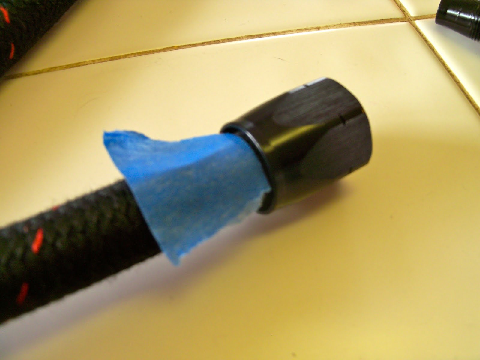
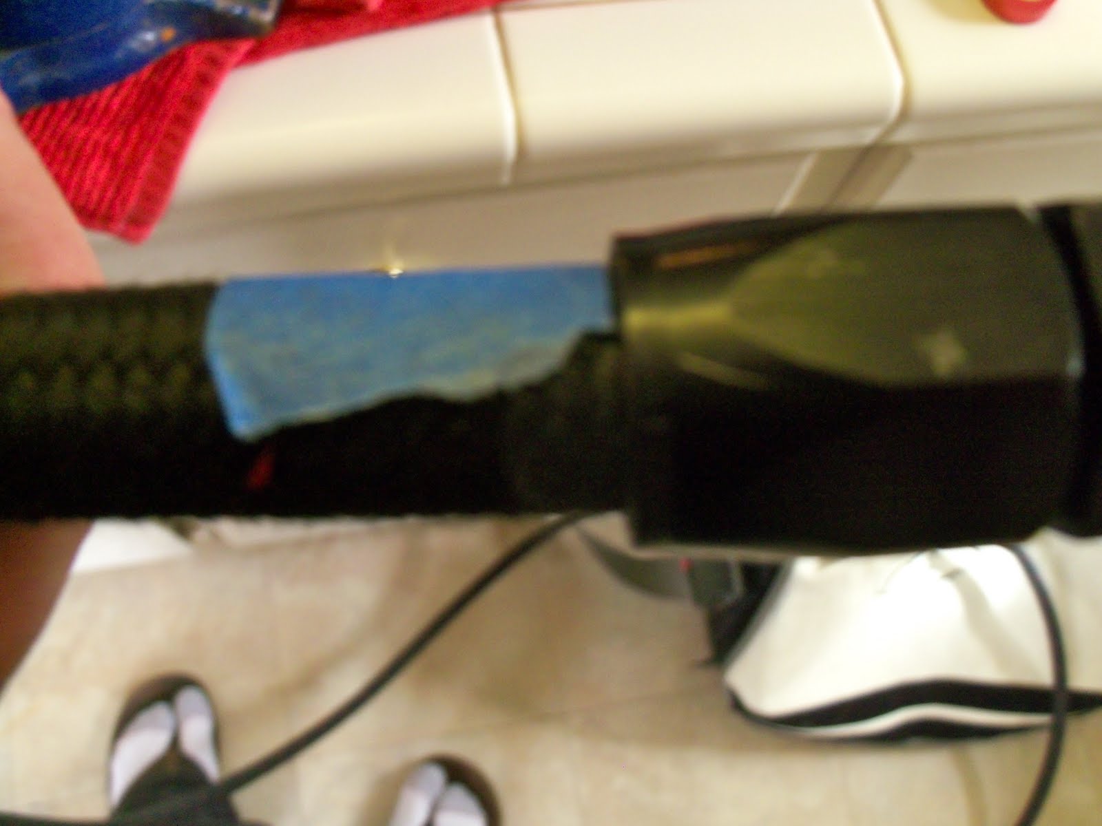
To attach the hose fitting, simply unthread the inside from the outside and slip the hose into the tapered end of the outside until it bottoms out as shown above. I did not use any guide, tool, or tape to aid the braided line's installation into the outer fitting. Put some tape on the hose at the edge of the fitting so that you know if the hose starts to back out during assembly. If it starts to back out you may be able to push it back in, if not simply back out the center piece until you can and start over.


With all the needed tools on the kitchen island counter and audience watching, this including the vise from downstairs, place the magnetic jaws into the vise, and the hose with the outer fitting installed on it into the jaws. There are several orientations of fitting-to-jaw that could be used depending on your jaws. I would recommend the magnetic ones with different mounting directions to make things easier, they're not much more expensive and make assembly easier.
If you are thinking what I was thinking before ordering them, then yes, if you only had (2) of the specific -an sized wrench you were assembling with you would not need the expensive kit or the jaws, but what if you need to assembly two different sized -an lines? What if three? Buying the jaws and one kit saves the trouble of buying 2 whole kits, and again, I would much rather have one or two extra tools than be caught missing one I needed, not to mention waste money in the long run by buying wrenches one off.


Tighten the vise, and indirectly the vise jaws, down on the outer fitting, making sure the tape is visible during assembly. Insert the inner fitting into the braided line and push down and turn to engage the threads. Tighten the inner fitting into the outer with the appropriately sized -an wrench, in this case pink, until the nut portion of the fittings almost touch each other. Again, make sure to do this slow and steady enough that the braided line does not back out as shown by the tape moving away from the outer part of the fitting. Sometimes it seems to help if you push the hose into the outer fitting from the other side as you are tightening the inner portion, but then again maybe that was my imagination. I did not use any lube or oil on the inner part of the fitting prior to assembly. I left it as tight as it would go without the outer/inner fitting faces touching, and more for aesthetic reasons, making sure the nut faces were in line with each other.


When making lines make sure to measure correctly. It's expensive to re-cut. I cut them long enough to allow the line to return straight before entering the next fitting. The hose has a minimum radius bend rating, but rather than try to find it and attempt to quantify it in practice, simply attach one fitting and loop it around as it will be installed, making sure it doesn't kink how it flows. When cutting precisely make sure to take into account the thickness of the outer fittings on either end as the hose needs to be long enough to be inserted fully into this portion of the fittings length on either side.
Here's a teaser of how it will be installed, but this post is running long so it will be continued another evening.

I wanted a full -an fitting braided fuel line system in the 24o z this time around. Not in the least so that Giffin would stop riding me about my car being about as safe as <insert joke here>, I was willing to put in the effort to do it right, as with every other part of the build.
One of the CTQ's of this build (like that acronym?, blame work) was that the body not be modified. I would consider a fuel cell installation a major body modification, so it was decided to stick with the OEM fuel tank. I needed to pull it for various reasons, including replacing the vent and filler lines, as well as inspecting the car underside and inside the tank to determine steps moving forward.


Caught in the act!
As possibly seen in a previous post, the inside of the tank was immaculate. Based on the rest of the car I have come to expect nothing less, but it still ups the spirits. It seemed like a good idea to do this part of the build inside because the -an lines were already there, along with associated tools, and my entire rear suspension for that matter. I was also running out of room in the garage, if you can believe it, and I considered this clean detail work that could be well performed in my kitchen. More importantly, it was cold outside.


Remove the OEM fuel pump.
Previously, the fuel level sender was removed, as well as the pickups on the forward side of the tank. This was after much thought as to how I was going to mount the fuel filter and pump, route the feed and return lines, as well as convert the system to -an braided without the use of a fuel cell. I refused to use a hose to -an barb adapter fitting under relative pressure because that one connection defeats the entire purpose of a braided/fitting fuel system. I also refused to hose clamp the open end of an -an hose onto a nipple fitting, say the OEM ones on the tank. Again, talk about a weak link in the system.
These requirements poised some interesting problems. On top of not wanting to defeat the whole safety aspect of this portion of the build, I did not want the performance of flow to be adversely affected by one small link, otherwise known as the internal OEM fuel tank pickup. Whats the point of large free flowing fittings and lines if it's sucking from a hole half the size?
One step at a time.


It didn't take me long to locate my walbro 255hp inline pump from the 28o z. I actually used it last to siphon gas from Jake's 6oo rr before he moved. Apparently movers don't like to transport a bike full of gas. It still had the barb fittings on either end which I used while it was in the 28o. These would be replaced later in stages, no need to rush into things.
In the 24o the OEM pump mounts directly to the tank as shown above, but in the 28o it mounted to a plate on the underside of the car near the passenger rear control arm. In either case it's an OEM inline pump, so replacing it with another inline pump did not affect the original design or require major tank retrofits, at least with respect to the pump type.
I was still surprised, nonetheless, when looking at the OEM pump on the 24o attached to the tank. It was yet another change in plan, but this time I think it worked out well. The walbro pump came with a kit which included some isolation foam to protect it as well as a pair of simple mounting brackets. On the 28o, the new pump actually installed in the stock location, with the extra foam, utilizing the stock mounts. After 4 years, and not to mention at least 3 states and 5 moves later, taking a little more time to find than the walbro itself, I dug up the brackets from a random tote in my bedroom in order to mount it on the 24o.


For once, I was able to kill 2 birds with 1 stone. In the 28o I used a simple OE inline barb filter that hung precariously between the tank nipple and the pump. Because of the above rant about fittings, weak links and the like, I sourced a new 1o micron inline filter from summit. It's got a replaceable filter and a high pressure flow with more filtering and most importantly, built in -an fittings. It was too big to really leave hanging in no-mans-land though and I had yet to buy mounts, or even decide how or where to use them when I did, but once I unwrapped it, it looked interestingly enough the same size as the pump. A quick test fit confirmed that another pump kit would be perfect, and I ordered one.
The OEM pump mounting holes on the tank seam were perfectly spaced to mount the pump and the filter back to back with using the pair of walbro mounting kits. It's almost like it was designed that way.


I ordered 5' of -8an push-lok hose designed for submerged in-tank use. I also ordered (2) -8an male/male bulkhead fitting, (1) -8an 90* female/barb fitting, and (1) package of russel -8an bulkhead nylon washers. My first idea was to use weld on -8an male fittings to avoid leaks and finish off the tank professionally, which I ordered (2) of initially, but realized really quickly that the only way the feed side would work in the stock location was if it also had an internal pickup, otherwise the bung would have to be located at the bottom of the tank or in a sump as in a fuel cell. Bulkhead fittings ultimately eliminated the need for a welder who would even touch a fuel tank. I decided to piece together my pickup kit because I didn't think 18" of hose was enough to loop over the divider inside the tank and around to an end position near the rear, center of the tank.
In retrospect I probably could have ordered the kit, but the aeroquip fittings are nice and for an extra few bucks, at least I had the option to determine my pickup location. In either case, I returned the weld on fittings.


The aeroquip fittings don't come with their own nuts, so be sure to order matching ones. I opted to use the 90* bend to simulate the OEM routing of the fuel pickup. I did not want the internal flexible line to be laying across the sharp edge of the inside divider within the fuel tank. Even though it would probably take ages for it to wear through if at all, it just seemed better to support the line such that it cleared over the barrier.


A package of stainless steel zipties later and I had a looped and secured 5' fuel pickup line. The idea was that the increased length coiled inside the fuel tank would help stage the fuel during hard cornering as there was no baffles or foam to keep the fuel from sloshing. After thinking more about this possibility, all that the increased line length would do is stay off the inevitable air bubble of starvation a few moments longer.


The only holes big enough to route the line through were the filler and fuel sender, and neither were really big enough to bend and squeeze 3-4 thicknesses of -8 line through without scraping the outsides to shreds. Not that I thought the ziptie would work it's way off and get stuck inside the tank on the other side of the barrier, but I wasn't looking forward to ever having to remove the coiled line, assuming of course that I was able to ever get it inside and positioned correctly in the first place.
I decided to try it without the ziptie and inserted it as laid above. With the bulkhead loosely in place to replicate the feed line's ultimate position, the end of the pickup line was nowhere near the right location. It sat up exactly as it does in the picture above, reducing the usable fuel line in the tank to almost nothing. I might as well have welded in those weld on fittings without a fuel pickup onto the stock location to begin with. After an hour of trying to adjust it inside the tank with a coat hanger and a flashlight, I pulled the line back out, thanking myself that I had not wasted even more time in both directions with the ziptie idea. Assuming it only goes in once, however, and never has to come out again, but was cut perfectly to begin with, tied in the exact location, and rotated precisely to place the end in the center rear part of the tank, the ziptie would have worked great.
Not going to risk it this time, so before cutting the line shorter, I moved onto something else entirely.


Braided fuel line.
If it's not apparent, my entire fuel system is -8an braided flex lines connecting 1/2" hard lines. All the fittings are aeroquip except for the hardline to hose junctions which were earls only because they came in one box. The aeroquip ones looked like they needed nuts, bushings, collars, and possibly sleeves, all of which had to be ordered separately and I was in no mood to order all but one piece and have to wait longer and deal with someone's customer service who may or may not know what was needed. All the fittings are anodized black with the exception of the earls which are red/blue and the aeroquip -an to barb fitting shown above, the former of which are mounted under the car, the latter inside a tank. It didn't matter too much anyways since the aeroquip hard line fittings didn't come completely in black either.
As another side note, the fuel tank pickup -an to barb fitting is internal to a sealed tank and under suction from the pump - it in no way detracts from the function of the braided/fitting system external to the tank or inclusive as a complete system.


I've never put together braided fuel lines before, but now is as good a time as any to learn. I read up and even watched a few how-to youtube videos. Many people spend lots of money on special tools to cut, clean, cap off, and install these fittings, but most of it isn't needed.
Stainless steel braided lines always looked a bit hokey to me, more like they belonged on a NASCAR than anything else, hence the lack of red/blue earls fittings minus the aforementioned hard to soft line junctions that when mounted only show blue assuming they weren't completely hidden from view under the car. Stainless steel lines are also extremely overkill for fuel pressures (1ooo psi? really? maybe for FAA safety margins), and relatively heavy as a side effect. They are also harder to cut, cause your fingers to bleed when assembling, did I mention NASCAR?
I settled on starlite, black nomex braided flex hose from aeroquip. It's a bit more expensive than stainless steel braid, but made of a Kevlar weave, very lightweight, black in color with a red tracer thread, and doesn't bite back when assembling. The allowable pressures are still well over what is needed on a much more reasonable scale without any sacrifices - 5o psi rail pressure in the system as compared to 3oo max line pressures. I mean come on, it's bulletproof! I ordered a bit more in a few different sizes and plan to use it for all my vent lines as well, but that I'll save for a later entry.

If you care about the condition of your new fittings, all you'll need is a simple cutter, a set of -an vise magnets, and an -an wrench (set). If you don't, then all you'll need is a box cutter and (2) adjustable wrenches. After spending anywhere from 1o$ to 3o$ a fitting, and with over 2o fittings in the whole system, I would suggest spending the money and getting a nice aluminum wrench set. Summit sells a great set with their own wrap-up holder.
To attach the hose fitting, simply unthread the inside from the outside and slip the hose into the tapered end of the outside until it bottoms out as shown above. I did not use any guide, tool, or tape to aid the braided line's installation into the outer fitting. Put some tape on the hose at the edge of the fitting so that you know if the hose starts to back out during assembly. If it starts to back out you may be able to push it back in, if not simply back out the center piece until you can and start over.


With all the needed tools on the kitchen island counter and audience watching, this including the vise from downstairs, place the magnetic jaws into the vise, and the hose with the outer fitting installed on it into the jaws. There are several orientations of fitting-to-jaw that could be used depending on your jaws. I would recommend the magnetic ones with different mounting directions to make things easier, they're not much more expensive and make assembly easier.
If you are thinking what I was thinking before ordering them, then yes, if you only had (2) of the specific -an sized wrench you were assembling with you would not need the expensive kit or the jaws, but what if you need to assembly two different sized -an lines? What if three? Buying the jaws and one kit saves the trouble of buying 2 whole kits, and again, I would much rather have one or two extra tools than be caught missing one I needed, not to mention waste money in the long run by buying wrenches one off.


Tighten the vise, and indirectly the vise jaws, down on the outer fitting, making sure the tape is visible during assembly. Insert the inner fitting into the braided line and push down and turn to engage the threads. Tighten the inner fitting into the outer with the appropriately sized -an wrench, in this case pink, until the nut portion of the fittings almost touch each other. Again, make sure to do this slow and steady enough that the braided line does not back out as shown by the tape moving away from the outer part of the fitting. Sometimes it seems to help if you push the hose into the outer fitting from the other side as you are tightening the inner portion, but then again maybe that was my imagination. I did not use any lube or oil on the inner part of the fitting prior to assembly. I left it as tight as it would go without the outer/inner fitting faces touching, and more for aesthetic reasons, making sure the nut faces were in line with each other.


When making lines make sure to measure correctly. It's expensive to re-cut. I cut them long enough to allow the line to return straight before entering the next fitting. The hose has a minimum radius bend rating, but rather than try to find it and attempt to quantify it in practice, simply attach one fitting and loop it around as it will be installed, making sure it doesn't kink how it flows. When cutting precisely make sure to take into account the thickness of the outer fittings on either end as the hose needs to be long enough to be inserted fully into this portion of the fittings length on either side.
Here's a teaser of how it will be installed, but this post is running long so it will be continued another evening.

No comments:
Post a Comment